Wind Turbine/en: Unterschied zwischen den Versionen
Shure (Diskussion | Beiträge) |
(fix math error by \begin{align}; some layout; pro and con in a table (no bullets); units with narrow-nbsp) |
||
| (Eine dazwischenliegende Version von einem anderen Benutzer wird nicht angezeigt) | |||
| Zeile 13: | Zeile 13: | ||
[[File:Etemu.com_TiVA_l2_front_wip.jpg|320px|thumb|left|3D Model of a [[TiVA]] rotor, work in progress. Note the hollow wings, this is a hybrid lift/drag wing profile with a full load TSR<ref>Tip Speed Ratio</ref> of 0.85.]] | [[File:Etemu.com_TiVA_l2_front_wip.jpg|320px|thumb|left|3D Model of a [[TiVA]] rotor, work in progress. Note the hollow wings, this is a hybrid lift/drag wing profile with a full load TSR<ref>Tip Speed Ratio</ref> of 0.85.]] | ||
| − | ==[[TiVA]]== | + | ==[[TiVA]]—Tiny Vertical Axis Wind Turbine== |
Research and development is currently concentrated onto [[TiVA]], a tiny wind turbine prototyping platform. With this very small turbine, we can easily change parts, try out new ideas and increase the performance on a small scale in a fast and inexpensive way. Please have a look at the [[TiVA]] page for further information. | Research and development is currently concentrated onto [[TiVA]], a tiny wind turbine prototyping platform. With this very small turbine, we can easily change parts, try out new ideas and increase the performance on a small scale in a fast and inexpensive way. Please have a look at the [[TiVA]] page for further information. | ||
| − | |||
| − | |||
[[File:Wilssen_core_v0.203a.brd_detail.png|512px|thumb|right|Detail of the PCB layout of the [[Wilssen]] core module. You can see the constant current sources on the left for the high brightness RGB LED. v203a (WIP)]] | [[File:Wilssen_core_v0.203a.brd_detail.png|512px|thumb|right|Detail of the PCB layout of the [[Wilssen]] core module. You can see the constant current sources on the left for the high brightness RGB LED. v203a (WIP)]] | ||
| − | |||
| − | |||
===Development of ''[[Wilssen]]''=== | ===Development of ''[[Wilssen]]''=== | ||
The '''''Wi'''reless'' / '''''Wi'''nd '''L'''ogging '''S'''ystem'' for '''''S'''ourcing '''EN'''ergy'' - Controller is monitoring and controlling all parameters. ''Wilssen'' is the brain of the wind turbines (+[[TiVA]]s!) and checks all the voltages at any time the wind turbine is generating power. | The '''''Wi'''reless'' / '''''Wi'''nd '''L'''ogging '''S'''ystem'' for '''''S'''ourcing '''EN'''ergy'' - Controller is monitoring and controlling all parameters. ''Wilssen'' is the brain of the wind turbines (+[[TiVA]]s!) and checks all the voltages at any time the wind turbine is generating power. | ||
| Zeile 44: | Zeile 40: | ||
=====Assembly height===== | =====Assembly height===== | ||
| − | The complete assembly of rotor and mast should not be higher than 10 m. If regional communities permit higher masts, the maximum height must not exceed 20 m, to avoid national and ICAO air traffic security issues and legal obligations to carry warning lights and report about their functionality. | + | The complete assembly of rotor and mast should not be higher than 10{{nnbsp}}m. If regional communities permit higher masts, the maximum height must not exceed 20{{nnbsp}}m, to avoid national and ICAO air traffic security issues and legal obligations to carry warning lights and report about their functionality. |
There are various restrictions in Germany present which depend on the size and location of a wind turbine: | There are various restrictions in Germany present which depend on the size and location of a wind turbine: | ||
| − | <blockquote>Verfahrensfrei sind Windenergieanlagen bis zu einer Höhe von 10 m<ref>Nummer 22 des Anhangs zu Paragraph 50 Abs. 1 LBO</ref>. In Mischgebieten<ref>Mischgebiet bedeutet gleichwertige Wohn- und Gewerbenutzung</ref> darf nachts ein Lärmrichtwert von 45 dB(A) nicht überschritten werden<ref>Auszug Windfibel Baden-Württemberg</ref>. Zu den Genehmigungsverfahren sei gesagt, dass die Landesbauordnung der jeweiligen Bundesländer / Kommunen unterschiedlich ist, also sollte man beim Bauamt nachfragen.</blockquote> | + | <blockquote>Verfahrensfrei sind Windenergieanlagen bis zu einer Höhe von 10{{nnbsp}}m<ref>Nummer 22 des Anhangs zu Paragraph 50 Abs. 1 LBO</ref>. In Mischgebieten<ref>Mischgebiet bedeutet gleichwertige Wohn- und Gewerbenutzung</ref> darf nachts ein Lärmrichtwert von 45{{nnbsp}}dB(A) nicht überschritten werden<ref>Auszug Windfibel Baden-Württemberg</ref>. Zu den Genehmigungsverfahren sei gesagt, dass die Landesbauordnung der jeweiligen Bundesländer / Kommunen unterschiedlich ist, also sollte man beim Bauamt nachfragen.</blockquote> |
=====Size===== | =====Size===== | ||
| − | We | + | We won’t start with a turbine greater than 4{{nnbsp}}m² due to restrictions in Europe pointed out by Detlef Schmitz. A wind surface of 4{{nnbsp}}m² equals a 2{{nnbsp}}m diameter rotor with a height of 2{{nnbsp}}m. |
| − | Hint: In every wind condition, a 1 m diameter VAWT with a height of 4 m ( | + | Hint: In every wind condition, a 1{{nnbsp}}m diameter VAWT with a height of 4{{nnbsp}}m (4{{nnbsp}}m²) is more efficient than a 2{{nnbsp}}m × 2{{nnbsp}}m (4{{nnbsp}}m²) VAWT due to the higher rpm and better aerodynamic figures. Industrial VAWTs aim for a large height, not for a large diameter. |
| Zeile 59: | Zeile 55: | ||
We want to design a rather small VAWT with [[TiVA]], resulting in the following advantages: | We want to design a rather small VAWT with [[TiVA]], resulting in the following advantages: | ||
| − | + | {| class="booktable sortable" | |
| − | + | ! +{{nnbsp}}/{{nnbsp}}– | |
| − | + | ! Comment | |
| − | + | |- | |
| − | + | | + || DIY! People should be able to build them! → [[wikipedia:KISS_principle|KISS principle]] | |
| − | + | |- | |
| − | + | | + || less moving parts | |
| − | + | |- | |
| − | + | | + || does not necessarily have to be elevated, can stand on the ground | |
| − | + | |- | |
| − | + | | + || collects wind from every direction: no need for a directional control (+less mechanics, electronics) | |
| − | + | |- | |
| − | + | | + || has a smaller footprint | |
| − | + | |- | |
| − | + | | + || easier to design | |
| + | |- | ||
| + | | + || way more easy to build | ||
| + | |- | ||
| + | | + || does not need a variable pitch control for high wind speed/ high power designs | ||
| + | |- | ||
| + | | + || uses cheaper materials, less bearings and axles, less machining operations | ||
| + | |- | ||
| + | | + || maintenance is easier, as the generator is on the ground, no need for a lift or a breakdown of the turbine head | ||
| + | |- | ||
| + | | + || a modular design is possible in a certain range (e.g. building it higher/longer in any direction) | ||
| + | |- | ||
| + | | + || does not necessarily need moldings or 3D shapes like sophisticated VAWT turbine blades | ||
| + | |- | ||
| + | | – || lower rpm at the same rotor diameter, at the same wind surface area due to the partly reversed draft of the wings but: | ||
| + | |- | ||
| + | | + || can have a small diameter but a rather large height, thus more torque ''and'' more rpm | ||
| + | |} | ||
Main disadvantage against a horizontal axis wind turbine: | Main disadvantage against a horizontal axis wind turbine: | ||
| − | + | <div class="definition-inline"> | |
| − | + | ; – : less power output compared to a sophisticated HAWT design if wind direction does not change often and turbulence is low | |
| − | + | </div> | |
The small form factor alone yields the following advantages next to being diy-friendly: | The small form factor alone yields the following advantages next to being diy-friendly: | ||
| − | + | {| class="booktable sortable" | |
| − | + | ! +{{nnbsp}}/{{nnbsp}}– | |
| − | + | ! Comment | |
| − | + | |- | |
| − | + | | + || easier maintenance | |
| − | + | |- | |
| − | + | | + || mobility, less weight | |
| + | |- | ||
| + | | + || smaller impact on the environment/nature | ||
| + | |- | ||
| + | | + || lower system voltage and lower currents, less risky to operate | ||
| + | |- | ||
| + | | + || a smaller power rating results in a less complicated generator and inverter design | ||
| + | |- | ||
| + | | + || batteries can be charged quick & dirty with a simple charging circuit from a small wind turbine, which would not be possible with a high power wind turbine | ||
| + | |} | ||
Specialties about distributed energy sourcing with small wind turbines: | Specialties about distributed energy sourcing with small wind turbines: | ||
| + | {| class="booktable sortable" | ||
| + | ! +{{nnbsp}}/{{nnbsp}}– | ||
| + | ! Comment | ||
| + | |- | ||
| + | | || (tbd) Multiple smaller wind turbines may have more physical weight per sourced energy (kg/kW) versus one large one. | ||
| + | |- | ||
| + | | – || requires an additional electrical infrastructure between multiple smaller wind turbines versus one large one → more cables and balancing (electronics) | ||
| + | |- | ||
| + | | + || the grid can be laid out in such a way, that the turbines can be placed where the energy is needed the most, resulting in smaller run lengths of power cables and less power losses. | ||
| + | |- | ||
| + | | + || the small turbines can easily be moved to an area with a higher wind speed. This is interesting when it comes to structural or seasonal changes of the wind, e.g. when the trees grow leaves and form a barrier which decreases the ground wind speed or they form an alley/a tunnel which increases the wind speed, one may move the wind turbine to gain from the new environment. | ||
| + | |} | ||
| − | + | Simply said, it is more flexible to use many small turbines versus one large one. If a larger energy source is required, we connect multiple wind turbines in a local grid → distributed energy sourcing, a 'wind farm' consisting of VAWTs: | |
| − | |||
| − | |||
| − | |||
| − | |||
| − | |||
| − | Simply said, it is more flexible to use many small turbines versus one large one. If a larger energy source is required, we connect multiple wind turbines in a local grid | ||
[[File:flowe.jpg|thumb|alt=A VAWT testing space|The ''Caltech Field Laboratory for Optimized Wind Energy'' where arrays of closely spaced ''vertical axis wind turbines'' were tested.]] | [[File:flowe.jpg|thumb|alt=A VAWT testing space|The ''Caltech Field Laboratory for Optimized Wind Energy'' where arrays of closely spaced ''vertical axis wind turbines'' were tested.]] | ||
| Zeile 108: | Zeile 136: | ||
The energy is in the wind due to it's speed/local pressure differences. A wind turbine ''converts'' kinetic energy from the wind into mechanical energy. The VAWT yields energy as kinetic energy from the wind is absorbed by rotating wings. Wind is made up of moving air molecules which have mass - though not a lot. Any moving object with mass carries kinetic energy in an amount which is given by the equation<ref>http://www.reuk.co.uk/Calculation-of-Wind-Power.htm</ref>: | The energy is in the wind due to it's speed/local pressure differences. A wind turbine ''converts'' kinetic energy from the wind into mechanical energy. The VAWT yields energy as kinetic energy from the wind is absorbed by rotating wings. Wind is made up of moving air molecules which have mass - though not a lot. Any moving object with mass carries kinetic energy in an amount which is given by the equation<ref>http://www.reuk.co.uk/Calculation-of-Wind-Power.htm</ref>: | ||
| − | :Kinetic Energy = 0.5 | + | :Kinetic Energy = 0.5 × Mass × Velocity² |
where the mass is measured in kg, the velocity in m/s, and the energy is given in joules. | where the mass is measured in kg, the velocity in m/s, and the energy is given in joules. | ||
| − | Air has a known density (around 1.23 kg/m³ at sea level), so the mass of air hitting our wind turbine (which sweeps a known area) each second is given by the following equation: | + | Air has a known density (around 1.23{{nnbsp}}kg/m³ at sea level), so the mass of air hitting our wind turbine (which sweeps a known area) each second is given by the following equation: |
| − | :Mass/sec (kg/s) = Velocity (m/s) | + | :Mass/sec (kg/s) = Velocity (m/s) × Area (m²) × Density (kg/m³) |
And therefore, the power (i.e. energy per second) in the wind hitting a wind turbine with a certain swept area is given by simply inserting the mass per second calculation into the standard kinetic energy equation given above resulting in the following vital equation: | And therefore, the power (i.e. energy per second) in the wind hitting a wind turbine with a certain swept area is given by simply inserting the mass per second calculation into the standard kinetic energy equation given above resulting in the following vital equation: | ||
| − | :Power = 0.5 | + | :Power = 0.5 × Swept Area × Air Density × Velocity³ |
where Power is given in Watts (i.e. joules/second), the swept area in square meters, the Air density in kilograms per cubic meter, and the Velocity in meters per second. | where Power is given in Watts (i.e. joules/second), the swept area in square meters, the Air density in kilograms per cubic meter, and the Velocity in meters per second. | ||
| Zeile 126: | Zeile 154: | ||
A lift-type VAWT generates lift at almost the full 360 degree rotation, as long as you have a TSR<ref>https://en.wikipedia.org/wiki/Tip-speed_ratio</ref> >> 1 (TSR=Tip Speed Ratio), i.e when the blades are moving faster than the wind is moving. This lift principle is why airplanes fly. | A lift-type VAWT generates lift at almost the full 360 degree rotation, as long as you have a TSR<ref>https://en.wikipedia.org/wiki/Tip-speed_ratio</ref> >> 1 (TSR=Tip Speed Ratio), i.e when the blades are moving faster than the wind is moving. This lift principle is why airplanes fly. | ||
| − | Depending on the operating speed and wind speed, the blades will actually be in stall for differing segments of the rotation, and hence not much lift, or at least a minimal amount compared to the drag, which slows the turbine down to a TSR < 1. This occurs when the angle of attack (for a static blade!) is at a certain point, let's say about 15 degrees. The following video shows aerodynamic stall, investigated on a 2D wing profile through air velocity, pressure, and turbulence intensity. | + | Depending on the operating speed and wind speed, the blades will actually be in stall for differing segments of the rotation, and hence not much lift, or at least a minimal amount compared to the drag, which slows the turbine down to a TSR < 1. This occurs when the angle of attack (for a static blade!) is at a certain point, let's say about 15 degrees. The following video shows aerodynamic stall, investigated on a 2D wing profile through air velocity, pressure, and turbulence intensity. |
http://youtu.be/Ti5zUD08w5s | http://youtu.be/Ti5zUD08w5s | ||
| Zeile 139: | Zeile 167: | ||
The '''''E'''nhanced '''V'''ertical '''A'''xis Wind Turbine'' idea incorporates an intake manifold at the front which is always facing the direction where the strongest wind is coming from. The main disadvantage of the VAWT against a HAWT is reduced: There is no attacking wind which will work against the natural, clockwise rotation of the VAWT. This may result in an increased overall efficiency. | The '''''E'''nhanced '''V'''ertical '''A'''xis Wind Turbine'' idea incorporates an intake manifold at the front which is always facing the direction where the strongest wind is coming from. The main disadvantage of the VAWT against a HAWT is reduced: There is no attacking wind which will work against the natural, clockwise rotation of the VAWT. This may result in an increased overall efficiency. | ||
| − | + | {| class="booktable sortable" | |
| − | + | ! +{{nnbsp}}/{{nnbsp}}– | |
| − | + | ! Comment | |
| − | + | |- | |
| + | | + || No wind is working 'against' the turbine, contrary to a standard VAWT, where half of the turbine is exposed to wind which flows into the 'wrong' direction | ||
| + | |- | ||
| + | | + || The wind speed right at the turbine intake is increased <ref>The deflection at the front adds up two "surfaces" of wind. However, the resulting wind speed won't change drastically.</ref> | ||
| + | |- | ||
| + | | + || (tbd) less oscillating forces, the wind flow is about unidirectional at the turbine: less vibrations and less wear at the rotating parts, more static and less dynamic thrust at the bearings, less torque ripple and cyclical stress. | ||
| + | |- | ||
| + | | – || More material is used for the construction of an '''''EVA''' wt'': two bearings, arms and static wings. However, these additional parts are not difficult to manufacture, as the surfaces are all plane. | ||
| + | |} | ||
| − | + | <gallery mode="packed" widths="200" heights="200" > | |
| − | <gallery> | ||
File:ETEMUcom_EVAwt7_top_detailed_diagramm.jpg|Normal airflow in a VAWT at the maximum torque moment. Note the non-uniform airflow with varying surfaces as the turbine blades advance. | File:ETEMUcom_EVAwt7_top_detailed_diagramm.jpg|Normal airflow in a VAWT at the maximum torque moment. Note the non-uniform airflow with varying surfaces as the turbine blades advance. | ||
File:ETEMUcom_EVAwt8_intake.jpg|Airflow in the '''''EVA''' wt'' design. View from the top. | File:ETEMUcom_EVAwt8_intake.jpg|Airflow in the '''''EVA''' wt'' design. View from the top. | ||
| Zeile 156: | Zeile 191: | ||
Let's start with the base mount. | Let's start with the base mount. | ||
| − | As the design outlines state we won't start with a turbine greater than 4 m² due to restrictions in Europe pointed out by Detlef Schmitz. A wind surface of 4 m² equals a 2 m diameter rotor with a height of 2 m. | + | As the design outlines state we won't start with a turbine greater than 4{{nnbsp}}m² due to restrictions in Europe pointed out by Detlef Schmitz. A wind surface of 4{{nnbsp}}m² equals a 2{{nnbsp}}m diameter rotor with a height of 2{{nnbsp}}m. |
:<math>F_{pole} = \frac{1}{2} \times \rho \times C_d \times A_{wind} \times v_{wind}^2</math> | :<math>F_{pole} = \frac{1}{2} \times \rho \times C_d \times A_{wind} \times v_{wind}^2</math> | ||
| − | <math>\rho</math> = Density of air = about 1.2 Kg/m³ <br /> | + | <math>\rho</math> = Density of air = about 1.2{{nnbsp}}Kg/m³ <br /> |
<math>C_d</math> = Coefficient of drag = 1.0 (cylinder Re > 100) <br /> | <math>C_d</math> = Coefficient of drag = 1.0 (cylinder Re > 100) <br /> | ||
| − | <math>A_{wind}</math> = Area of turbine = max 4 m² <br /> | + | <math>A_{wind}</math> = Area of turbine = max 4{{nnbsp}}m² <br /> |
<math>v_{wind}</math> = Wind speed in m/s | <math>v_{wind}</math> = Wind speed in m/s | ||
| − | <math>F(50\frac{m}{s})=\frac{1}{2} \times 1.2\frac{kg}{m^3} \times 1.0 \times 4m^2 \times 50\frac{m}{s}^2 = 6000 N | + | <math> |
| − | + | \begin{align} | |
| − | + | F(50\frac{m}{s}) &= \frac{1}{2} \times 1.2\frac{kg}{m^3} \times 1.0 \times 4m^2 \times 50\frac{m}{s}^2 = 6000 N \\ | |
| − | + | F(30\frac{m}{s}) &= 2160N\\ | |
| − | + | F(20\frac{m}{s}) &= 960N \\ | |
| + | F(10\frac{m}{s}) &= 240N\\ | ||
| + | F(5\frac{m}{s}) &= 60N | ||
| + | \end{align} | ||
| + | </math> | ||
TODO: Leverage should be taken into account here. How to calculate the load at the bearing points? | TODO: Leverage should be taken into account here. How to calculate the load at the bearing points? | ||
| Zeile 185: | Zeile 224: | ||
|---- | |---- | ||
|50-year-maximum | |50-year-maximum | ||
| − | |50 m/s | + | |50{{nnbsp}}m/s |
| − | |42 | + | |42.5{{nnbsp}}m/s |
| − | |37 | + | |37.5{{nnbsp}}m/s |
| − | |30 m/s | + | |30{{nnbsp}}m/s |
|---- | |---- | ||
|average wind speed | |average wind speed | ||
| − | |10 m/s | + | |10{{nnbsp}}m/s |
| − | |8 | + | |8.5{{nnbsp}}m/s |
| − | |7 | + | |7.5{{nnbsp}}m/s |
| − | |6 m/s | + | |6{{nnbsp}}m/s |
|---- | |---- | ||
|} | |} | ||
| − | Example for a classification in Germany, Berlin: The mean wind speed is classified above IEC class IV with an average value of 2. | + | Example for a classification in Germany, Berlin: The mean wind speed is classified above IEC class IV with an average value of 2.3–3.6{{nnbsp}}m/s at ground level <ref>equals a mast height of 10{{nnbsp}}m or below</ref> without any obstacles. |
| − | IEC classes are realistic for higher wind zones, industrial wind turbines are usually mounted at >50 m. We are safe with an IEC class IV design. The design should be build for a maximum load of <math>F(30\frac{m}{s})=2160N</math>. | + | IEC classes are realistic for higher wind zones, industrial wind turbines are usually mounted at >{{nnbsp}}50 m. We are safe with an IEC class IV design. The design should be build for a maximum load of <math>F(30\frac{m}{s})=2160N</math>. |
==Estimating the power output of the VAWT== | ==Estimating the power output of the VAWT== | ||
| Zeile 209: | Zeile 248: | ||
<math>P_{wind}</math> is the power, which is available in the wind. It is available as kinetic energy due to the moving mass of the air.<br /> | <math>P_{wind}</math> is the power, which is available in the wind. It is available as kinetic energy due to the moving mass of the air.<br /> | ||
| − | <math>\rho</math> = Density of air = about 1.2 Kg/m³ <br /> | + | <math>\rho</math> = Density of air = about 1.2{{nnbsp}}Kg/m³ <br /> |
| − | <math>A_{wind}</math> = Area of turbine = max 4 m² at a small scale turbine <br /> | + | <math>A_{wind}</math> = Area of turbine = max 4{{nnbsp}}m² at a small scale turbine <br /> |
<math>v_{wind}</math> = Wind speed in m/s <br /> | <math>v_{wind}</math> = Wind speed in m/s <br /> | ||
| Zeile 218: | Zeile 257: | ||
:<math>P_{mech}=P_{wind} \times \rho_{turbine} </math> | :<math>P_{mech}=P_{wind} \times \rho_{turbine} </math> | ||
| − | while <br | + | while <br /> |
<math> | <math> | ||
| − | \rho_{simple} = 20\% \\ | + | \begin{align} |
| − | \rho_{decent} = 30\% \\ | + | \rho_{simple} &= 20\% \\ |
| − | \rho_{good} = 35\% \\ | + | \rho_{decent} &= 30\% \\ |
| − | \rho_{superbVAWT} = 40\% \\ | + | \rho_{good} &= 35\% \\ |
| − | \rho_{superbHAWT} = 50\% \\ | + | \rho_{superbVAWT} &= 40\% \\ |
| − | \rho_{limit} = 59\% \ | + | \rho_{superbHAWT} &= 50\% \\ |
| − | </math><br | + | \rho_{limit} &= 59\% |
| + | \end{align} | ||
| + | </math><br /> | ||
A tuned VAWT may have a best-case efficiency of 40%<ref>Can the EVAwt design yield more? Tbd!</ref>, while a simple drag-based turbine with no optimization nor special aerodynamics may have an efficiency of about 20%. | A tuned VAWT may have a best-case efficiency of 40%<ref>Can the EVAwt design yield more? Tbd!</ref>, while a simple drag-based turbine with no optimization nor special aerodynamics may have an efficiency of about 20%. | ||
| Zeile 245: | Zeile 286: | ||
<references /> | <references /> | ||
| − | [[Category: | + | [[Category: OSEG - Bereich Technologie]] |
| − | [[Category: | + | [[Category: OSEG - Windenergie]] |
[[Category: Energie]] | [[Category: Energie]] | ||
[[Category: Wind]] | [[Category: Wind]] | ||
[[Category: Turbine]] | [[Category: Turbine]] | ||
Version vom 30. Mai 2018, 13:36 Uhr
![]()
Status
This project is not in active development. The information on this page is obsolete and outdated.
Introduction
All information is released open source and for free, for a better world and for the fun of open collaboration. (CC BY-SA-NC)

TiVA—Tiny Vertical Axis Wind Turbine
Research and development is currently concentrated onto TiVA, a tiny wind turbine prototyping platform. With this very small turbine, we can easily change parts, try out new ideas and increase the performance on a small scale in a fast and inexpensive way. Please have a look at the TiVA page for further information.

Development of Wilssen
The Wireless / Wind Logging System for Sourcing ENergy - Controller is monitoring and controlling all parameters. Wilssen is the brain of the wind turbines (+TiVAs!) and checks all the voltages at any time the wind turbine is generating power.
Others
- Design a mold for casting the alternator's stator
- 3D Models and Simulation
- Calculations for the forces at the bearing points and the mounting point
- LED drivers, controllable constant current sources for the high power LEDs
Roadmap / Log

General design outlines
The wind turbine should be loosely designed according to the OSE Core Values except points 8 and 9, which demand high performance and equal to or higher than industrial efficiency [3]
In addition to the OSE Core Values, the wind turbine should be safe to operate, e.g. have a suitable safety factor in all structural calculations, proper isolation to prevent an electric shock.
Assembly height
The complete assembly of rotor and mast should not be higher than 10 m. If regional communities permit higher masts, the maximum height must not exceed 20 m, to avoid national and ICAO air traffic security issues and legal obligations to carry warning lights and report about their functionality. There are various restrictions in Germany present which depend on the size and location of a wind turbine:
Verfahrensfrei sind Windenergieanlagen bis zu einer Höhe von 10 m[4]. In Mischgebieten[5] darf nachts ein Lärmrichtwert von 45 dB(A) nicht überschritten werden[6]. Zu den Genehmigungsverfahren sei gesagt, dass die Landesbauordnung der jeweiligen Bundesländer / Kommunen unterschiedlich ist, also sollte man beim Bauamt nachfragen.
Size
We won’t start with a turbine greater than 4 m² due to restrictions in Europe pointed out by Detlef Schmitz. A wind surface of 4 m² equals a 2 m diameter rotor with a height of 2 m. Hint: In every wind condition, a 1 m diameter VAWT with a height of 4 m (4 m²) is more efficient than a 2 m × 2 m (4 m²) VAWT due to the higher rpm and better aerodynamic figures. Industrial VAWTs aim for a large height, not for a large diameter.
We want to design a rather small VAWT with TiVA, resulting in the following advantages:
| + / – | Comment |
|---|---|
| + | DIY! People should be able to build them! → KISS principle |
| + | less moving parts |
| + | does not necessarily have to be elevated, can stand on the ground |
| + | collects wind from every direction: no need for a directional control (+less mechanics, electronics) |
| + | has a smaller footprint |
| + | easier to design |
| + | way more easy to build |
| + | does not need a variable pitch control for high wind speed/ high power designs |
| + | uses cheaper materials, less bearings and axles, less machining operations |
| + | maintenance is easier, as the generator is on the ground, no need for a lift or a breakdown of the turbine head |
| + | a modular design is possible in a certain range (e.g. building it higher/longer in any direction) |
| + | does not necessarily need moldings or 3D shapes like sophisticated VAWT turbine blades |
| – | lower rpm at the same rotor diameter, at the same wind surface area due to the partly reversed draft of the wings but: |
| + | can have a small diameter but a rather large height, thus more torque and more rpm |
Main disadvantage against a horizontal axis wind turbine:
- –
- less power output compared to a sophisticated HAWT design if wind direction does not change often and turbulence is low
The small form factor alone yields the following advantages next to being diy-friendly:
| + / – | Comment |
|---|---|
| + | easier maintenance |
| + | mobility, less weight |
| + | smaller impact on the environment/nature |
| + | lower system voltage and lower currents, less risky to operate |
| + | a smaller power rating results in a less complicated generator and inverter design |
| + | batteries can be charged quick & dirty with a simple charging circuit from a small wind turbine, which would not be possible with a high power wind turbine |
Specialties about distributed energy sourcing with small wind turbines:
| + / – | Comment |
|---|---|
| (tbd) Multiple smaller wind turbines may have more physical weight per sourced energy (kg/kW) versus one large one. | |
| – | requires an additional electrical infrastructure between multiple smaller wind turbines versus one large one → more cables and balancing (electronics) |
| + | the grid can be laid out in such a way, that the turbines can be placed where the energy is needed the most, resulting in smaller run lengths of power cables and less power losses. |
| + | the small turbines can easily be moved to an area with a higher wind speed. This is interesting when it comes to structural or seasonal changes of the wind, e.g. when the trees grow leaves and form a barrier which decreases the ground wind speed or they form an alley/a tunnel which increases the wind speed, one may move the wind turbine to gain from the new environment. |
Simply said, it is more flexible to use many small turbines versus one large one. If a larger energy source is required, we connect multiple wind turbines in a local grid → distributed energy sourcing, a 'wind farm' consisting of VAWTs:

Dabiri carried out field tests in the summer of 2010 at an experimental farm known as the Field Laboratory for Optimized Wind Energy (FLOWE), which houses 24 10-meter-tall, 1.2-meter-wide VAWTs. In the field tests, which used six VAWTs, Dabiri and his colleagues measured the rotational speed and power generated by each of the turbines when placed in a number of different configurations. One turbine was kept in a fixed position for every configuration, while the others were on portable footings that allowed them to be shifted around.
They found that the aerodynamic interference between neighboring turbines was completely eliminated when all the turbines in an array were spaced four turbine diameters (roughly five meters or 16 feet) apart. In comparison, propeller-style HAWTs would need to be spaced 20 rotor diameters apart - which equates to a distance of more than one mile for the largest wind turbines currently in use - for the aerodynamic interference to be eliminated.
The six VAWTs generated from 21 to 47 watts of power per square meter of land area, while a comparably sized HAWT farm generates just two to three watts per square meter. See video and reference. [7]
How does the wind turbine generate energy?
The energy is in the wind due to it's speed/local pressure differences. A wind turbine converts kinetic energy from the wind into mechanical energy. The VAWT yields energy as kinetic energy from the wind is absorbed by rotating wings. Wind is made up of moving air molecules which have mass - though not a lot. Any moving object with mass carries kinetic energy in an amount which is given by the equation[8]:
- Kinetic Energy = 0.5 × Mass × Velocity²
where the mass is measured in kg, the velocity in m/s, and the energy is given in joules.
Air has a known density (around 1.23 kg/m³ at sea level), so the mass of air hitting our wind turbine (which sweeps a known area) each second is given by the following equation:
- Mass/sec (kg/s) = Velocity (m/s) × Area (m²) × Density (kg/m³)
And therefore, the power (i.e. energy per second) in the wind hitting a wind turbine with a certain swept area is given by simply inserting the mass per second calculation into the standard kinetic energy equation given above resulting in the following vital equation:
- Power = 0.5 × Swept Area × Air Density × Velocity³
where Power is given in Watts (i.e. joules/second), the swept area in square meters, the Air density in kilograms per cubic meter, and the Velocity in meters per second.

A lift-type VAWT generates lift at almost the full 360 degree rotation, as long as you have a TSR[9] >> 1 (TSR=Tip Speed Ratio), i.e when the blades are moving faster than the wind is moving. This lift principle is why airplanes fly. Depending on the operating speed and wind speed, the blades will actually be in stall for differing segments of the rotation, and hence not much lift, or at least a minimal amount compared to the drag, which slows the turbine down to a TSR < 1. This occurs when the angle of attack (for a static blade!) is at a certain point, let's say about 15 degrees. The following video shows aerodynamic stall, investigated on a 2D wing profile through air velocity, pressure, and turbulence intensity.
However, the dynamic stall characteristics are significantly different though, and since the angle of attack for a Darrieus turbine with lift airfoils is constantly changing, dynamic stall is much more important. For us, this is still rocket science and can't be measured. It has to be simulated with CFD/FEA and we hope to have some results about various wing types soon as Achmed from OSE Germany is working on a simulation with OpenFoam, an Open Source CFD program for Linux.
A drag type VAWT has always a TSR <1, and the blades capture energy for more or less 180 degrees, the blades fight the wind the other 180 degrees.
EVA wind turbine

The Enhanced Vertical Axis Wind Turbine idea incorporates an intake manifold at the front which is always facing the direction where the strongest wind is coming from. The main disadvantage of the VAWT against a HAWT is reduced: There is no attacking wind which will work against the natural, clockwise rotation of the VAWT. This may result in an increased overall efficiency.
| + / – | Comment |
|---|---|
| + | No wind is working 'against' the turbine, contrary to a standard VAWT, where half of the turbine is exposed to wind which flows into the 'wrong' direction |
| + | The wind speed right at the turbine intake is increased [11] |
| + | (tbd) less oscillating forces, the wind flow is about unidirectional at the turbine: less vibrations and less wear at the rotating parts, more static and less dynamic thrust at the bearings, less torque ripple and cyclical stress. |
| – | More material is used for the construction of an EVA wt: two bearings, arms and static wings. However, these additional parts are not difficult to manufacture, as the surfaces are all plane. |
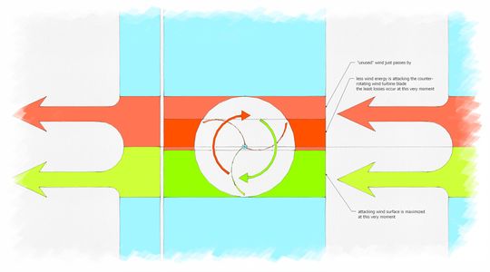
Normal airflow in a VAWT at the maximum torque moment. Note the non-uniform airflow with varying surfaces as the turbine blades advance.
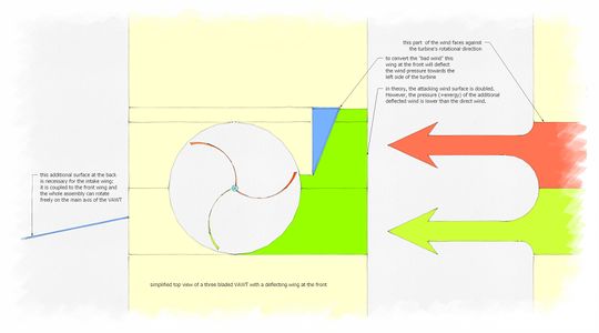
Airflow in the EVA wt design. View from the top.
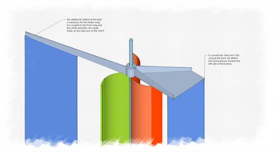
Example of a simple constructional integration of the EVA wt design with sheet material. ISO-View from the top.


Calculations and Simulations

All calculations are made in the metric system.
Let's start with the base mount. As the design outlines state we won't start with a turbine greater than 4 m² due to restrictions in Europe pointed out by Detlef Schmitz. A wind surface of 4 m² equals a 2 m diameter rotor with a height of 2 m.

= Density of air = about 1.2 Kg/m³
= Coefficient of drag = 1.0 (cylinder Re > 100)
= Area of turbine = max 4 m²
= Wind speed in m/s


TODO: Leverage should be taken into account here. How to calculate the load at the bearing points?
TODO: Consider serious safety factor for robustness and against oscillations.
Maximum wind speed the turbine has to withstand:
| IEC wind class | I | II | III | IV |
| 50-year-maximum | 50 m/s | 42.5 m/s | 37.5 m/s | 30 m/s |
| average wind speed | 10 m/s | 8.5 m/s | 7.5 m/s | 6 m/s |
Example for a classification in Germany, Berlin: The mean wind speed is classified above IEC class IV with an average value of 2.3–3.6 m/s at ground level [12] without any obstacles.
IEC classes are realistic for higher wind zones, industrial wind turbines are usually mounted at > 50 m. We are safe with an IEC class IV design. The design should be build for a maximum load of .

Estimating the power output of the VAWT
Power available in the wind:

is the power, which is available in the wind. It is available as kinetic energy due to the moving mass of the air.
= Density of air = about 1.2 Kg/m³
= Area of turbine = max 4 m² at a small scale turbine
= Wind speed in m/s

Power available from the turbine:
This is the estimated mechanical wind power conversion.

while

A tuned VAWT may have a best-case efficiency of 40%[13], while a simple drag-based turbine with no optimization nor special aerodynamics may have an efficiency of about 20%.
Other links
- non OS example 1
- http://www.fundamentalform.com/html/involute_wind_turbine.html
- http://www.daswindrad.de/forum/viewtopic.php?f=2&t=21
- http://www.tinytechindia.com/windenergy.htm
- http://www.macarthurmusic.com/johnkwilson/MakingasimpleSavoniuswindturbine.htm A bit more efficient than a standard Savonius
- https://www.youtube.com/playlist?list=PL212B7C0D6057AC28 youtube playlist
Daniel
- http://www.youtube.com/user/danielturbin/videos?sort=dd&view=0 Wind is only one of many nice things he did
- http://www.maskinisten.net/viewtopic.php?t=8655 Forum with pictures and tests explained in Swedish
Sources
- ↑ Tip Speed Ratio
- ↑ work in progress
- ↑ OSE Core Values points 8 and 9 demand a high performance and equal to or higher than industrial efficiency but the efficiency of a highly sophisticated industrial, FEA designed and airflow-simulated, wind tunnel tested model can't be matched by a diy design.
- ↑ Nummer 22 des Anhangs zu Paragraph 50 Abs. 1 LBO
- ↑ Mischgebiet bedeutet gleichwertige Wohn- und Gewerbenutzung
- ↑ Auszug Windfibel Baden-Württemberg
- ↑ http://www.gizmag.com/optimizing-wind-turbine-placement/19217/
- ↑ http://www.reuk.co.uk/Calculation-of-Wind-Power.htm
- ↑ https://en.wikipedia.org/wiki/Tip-speed_ratio
- ↑ http://etemu.com/p/evawt/ETEMUcom_EVAwt6_iso.jpg
- ↑ The deflection at the front adds up two "surfaces" of wind. However, the resulting wind speed won't change drastically.
- ↑ equals a mast height of 10 m or below
- ↑ Can the EVAwt design yield more? Tbd!