Neue Dateien
Zur Navigation springen
Zur Suche springen
Diese Spezialseite zeigt die zuletzt hochgeladenen Dateien an.
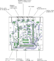
- Abbildung 15 Arduinoplatine und deren Schnittstellen.png Thomas Plaz
20:46, 6. Dez. 2019
700 × 793; 288 KB
- Abbildung 15 Arduinoplatine und deren Schnittstellen.svg Thomas Plaz
18:55, 6. Dez. 2019
0 × 0; 2,1 MB
- Abbildung 35 Systemaulsegung anhand des Exceltools.svg Thomas Plaz
05:35, 6. Dez. 2019
726 × 391; 20 KB
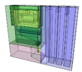
- Abbildung 34 Wechselrichteranordnung im Schaltschrank.svg Thomas Plaz
05:33, 6. Dez. 2019
737 × 436; 941 KB
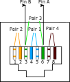
- Abbildung 33 CAT 5 Adapter mit Minischraubklemmen.svg Thomas Plaz
05:32, 6. Dez. 2019
744 × 1.052; 144 KB
- Abbildung 32 Modbuszähler Solar 1 Phasen Zähler.svg Thomas Plaz
05:29, 6. Dez. 2019
224 × 896; 146 KB
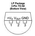
- Abbildung 29 Anschlusssituation Temperatursensor LM 35.svg Thomas Plaz
05:26, 6. Dez. 2019
261 × 265; 37 KB
- Abbildung 28 Einstellungen MQTT Node IN und OUT.svg Thomas Plaz
05:25, 6. Dez. 2019
730 × 434; 100 KB
- Abbildung 27 Flow für Wlan Steckdose gesteuert über MQTT Protokoll.svg Thomas Plaz
05:24, 6. Dez. 2019
729 × 152; 26 KB
- Abbildung 26 Konfiguration der Wlan Steckdose über das Webinterface.svg Thomas Plaz
05:23, 6. Dez. 2019
415 × 810; 73 KB
- Abbildung 25 Hierarchiestruktur MQTT Protokoll und definition des Prefix cmd, stat und tele.svg Thomas Plaz
05:22, 6. Dez. 2019
738 × 222; 99 KB
- Abbildung 24 Weboderfläche der Wlan Steckdose mit der IP 192.168.1.5.svg Thomas Plaz
05:21, 6. Dez. 2019
554 × 385; 28 KB
- Abbildung 22 Hashcode und Passworteingabe für Node Red.svg Thomas Plaz
05:19, 6. Dez. 2019
731 × 187; 93 KB
- Abbildung 20.2 User Interface (Weboderfläche von Node Red).svg Thomas Plaz
05:16, 6. Dez. 2019
1.052 × 744; 188 KB
- Abbildung 20 Schaltplan für Taster Herunterfahren und Reset Raspberry.svg Thomas Plaz
21:04, 5. Dez. 2019
1.042 × 272; 145 KB
- Abbildung 19 Hutschienengehäuse für Raspberry Pi.svg Thomas Plaz
21:03, 5. Dez. 2019
741 × 371; 121 KB
- Abbildung 18 Kombinierte Arduino- und Mosfetplatine.svg Thomas Plaz
21:00, 5. Dez. 2019
1.027 × 601; 113 KB
- Abbildung 16 Mosfetplatine und deren Schnittstellen.svg Thomas Plaz
20:59, 5. Dez. 2019
0 × 0; 4,01 MB
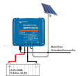
- Abbildung 10 Schnittstelle Laderegler Victron MPPT 100-15.svg Thomas Plaz
20:50, 5. Dez. 2019
1.006 × 357; 29 KB
- Abbildung 4.2 Stromeinspeisung ins Hausnetz (grün) und Stromverbrauch (blau)-001.jpg Thomas Plaz
20:33, 5. Dez. 2019
3.131 × 896; 384 KB
- Abbildung 9.2 Messung der Wirkungsgradkennlinie des Wechselrichters INV 350-60 von AE Conversion.svg Thomas Plaz
18:08, 5. Dez. 2019
737 × 398; 191 KB
- Abbildung 9 Kommunikation mit dem Wechselrichter über das Programm HTherm.svg Thomas Plaz
18:04, 5. Dez. 2019
712 × 108; 12 KB
- Abbildung 8 Kommunikationstest mit dem Wechselrichter mit dem Programm AE Solar.svg Thomas Plaz
17:57, 5. Dez. 2019
680 × 389; 137 KB
- Abbildung 7 Anschluss der RS485 Schnittstelle des Wechselrichters.svg Thomas Plaz
17:34, 5. Dez. 2019
415 × 490; 21 KB
- Abbildung 5 Systemkomponenten und deren Schnittstellen png.png Thomas Plaz
21:20, 4. Dez. 2019
567 × 388; 53 KB
- Abbildung 5 Systemkomponenten und deren Schnittstellen.pdf Thomas Plaz
19:30, 4. Dez. 2019
944 × 646; 34 KB
- Abbildung 2 Mietobjekt ohne und mit PV Speichersystem-001.pdf Thomas Plaz
12:15, 18. Nov. 2019
1.004 × 412; 522 KB
- Abbildung 4.1 Solarertrag (rot), Stromverbrauch (blau) und Stromeinspeisung ins Hausnetz (grün).pdf Thomas Plaz
12:10, 18. Nov. 2019
1.564 × 525; 282 KB
- Abbildung 1.1 GNU General Public License v3.0.pdf Thomas Plaz
21:12, 12. Nov. 2019
894 × 491; 153 KB
- Abbildung 2 Mietobjekt ohne und mit PV Speichersystem.pdf Thomas Plaz
21:08, 12. Nov. 2019
1.089 × 580; 8,07 MB
- Entwicklung eines Auslegungswerkzeuges für Stirlingmotoren (Bachelorarbeit von Martin Schott, 20. April 2015).pdf Case
18:51, 7. Nov. 2019
1.240 × 1.753, 70 Seiten; 3,79 MB
