Wind Logging System for Sourcing ENergy – WiLSSEN
| Description, License, Development Status | |
|---|---|
| Project: Wind Logging System for Sourcing ENergy — WiLSSEN. Description: A controller system as a multi-purpose prototyping platform for (but not limited to) renewable energies, e.g. it can be used for monitoring all electrical parameters of a wind turbine generator or to sense the temperature in a room/machine/garden/aquaponic system wirelessly for over one year on a set of two AA-batteries. | |
| Keywords | wind; energy; prototype logging; wind turbine; sensory logging |
| License | Attribution-ShareAlike 4.0 International (CC BY-SA 4.0) |
| Status | inactive |
| Levels Achieved | prototype development |
| Communication | |
| Contact |
|
| Creators, Contributors | Please add creators or contributors |
| Discussion |
|
Introduction
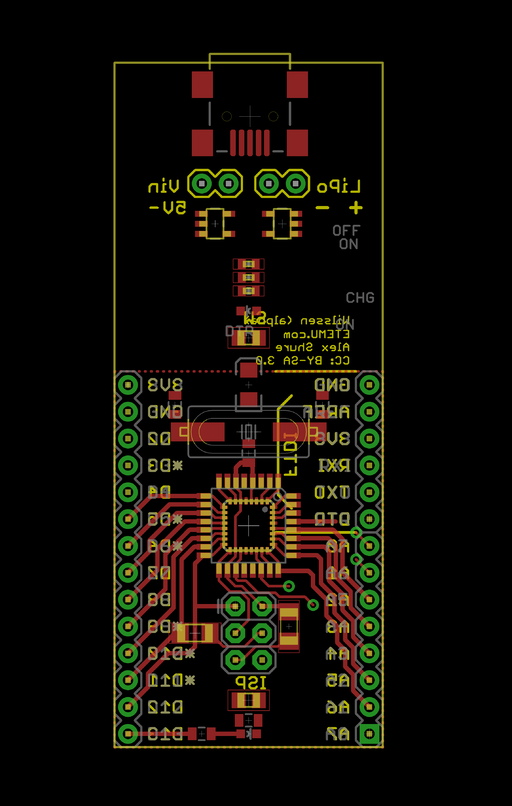
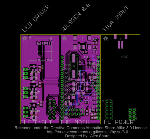
The Wireless / Wind Logging System for Sourcing ENergy - Controller is a multi-purpose prototyping platform for (but not limited to) renewable energies. E.g. It can be used for monitoring all electrical parameters of a wind turbine generator or to sense the temperature in a room/machine/garden/aquaponic system wirelessly for over one year on a set of two AA-batteries.[1]
Wilssen is the brain of TiVA and checks all the voltages at any time the wind turbine is generating power.
Hardware
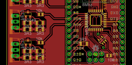
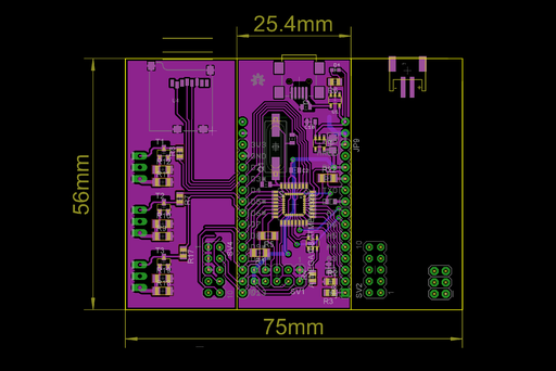
- NRF24L01+ 2.4Ghz wireless communication. Mesh networking would be awesome :) - cluster networking should be possible with this Arduino library: http://maniacbug.wordpress.com/2012/03/30/rf24network/
- RGB LED PWM output (3 channels, R+G+B)
Current sensing:
- Passive on-board shunt resistor (only for low currents) via OpAmp -> 10bit ADC
- Allegro ACS712 integrated hall sensor with drift compensation, 1.2 mOhms (5A, 20A, 50A versions available) -> 10bit ADC
Voltage sensing:
- Passive resistor divider with high impedance coupling -> 10bit< ADC
- optional: decoupled voltage sensing via IC / galvanic isolation.
- (tbd) Option for waveform sampling, softscope (e.g. output the waveform at a specified sample interval in 10bit via serial over the wireless link)
- (tbd) Logging on MicroSD
- (tbd) Charging circuit for 4 NiMH cells / 1 lead acid gel battery.
Main Controller: Wilssen core
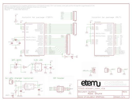
- Optiboot bootloader compatible, thus Arduino compatible
- Main MCU: Atmel Atmega168, Atmega328
Software
Microcontroller
- RGB LED library
- Logic power supply battery voltage monitoring / watchdog
- Variable voltage protection routine
- Variable current protection routine
- Wireless communication protocol
- RPM calculation from alternator frequency
- MicroSD logging
- Sleep mode
- (tbd)
Computer
- GUI for real time analysis
Communications
This is a draft for the communications.
We need a transparent protocol for seperate layers of communication;
If there is only one WiLSSEN controller (a single leaf node) and you wire it to a PC/Mac:
- (serial) WiLSSEN leaf node <-> host
For a stationary installation, for example in your garden or on the roof without a wired connection:
- (wireless) WiLSSEN leaf node <-> WiLSSEN gateway [exit node] <-> host|LAN|WAN
When combining WiLSSEN controllers in a peer to peer network:
- (wireless) WiLSSEN node <-> WiLSSEN node <-> WiLSSEN node ( <-> host)
The gateway node needs to forward any traffic from the nodes to a connected host via serial or to the LAN/WAN via ethernet:
- (serial/eth) WiLSSEN gateway <-> host|LAN|WAN
A gateway always listens for traffic and handles it accordingly. A leaf node may sleep for extended periods, only waking up for the occasional keep-alive packet and status report. If it is not busy with a task, it should sleep and power off the communication electronics. Except when it is in debug mode, of course.
Network with multiple WiLSSEN nodes
Nodes are automatically configured in a tree topology, according to their node address. Nodes can only directly communicate with their parent and their children. The network will automatically send messages to the right place:
Node 00 is the ‘base’ node. Nodes 01-05 directly communicate with Node 00, but not with each other. So for Node 01 to send a message to Node 02, it will travel through Node 00. Nodes 011, 021, 031 and so on are children of Node 01. For Node 011 to send to 02, it will send to 01, then to 00, then to 02. Therefore, if you put a Node 011 on your network, be sure that there is a Node 01 on the network, and it’s powered up, and it’s in range! [5]
If there is a missing branch in the tree aka. a node is down, then the communication which is piped through that very node won't be handled. A fix for this would be to implement a self-organizing mesh network. However, a single NRF24 chip has only a few communication pipes and the the implementation of a true mesh network is a lot more sophisticated than a hard coded tree or star topology.
The WiLSSEN protocol
Nodes can communicate over the wireless network with the WiLSSEN protocol. ManiacBug's RF24Network library[6] is used for the Nordic NRF24L01+ wireless module interfacing.
The RF24Network sends two pieces of information out on the wire in each frame, a header and a message. The header is defined by the library, and used to route frames to the correct place, and provide standard information. This is defined in RF24Network.h:
/**
* Header which is sent with each message
*
* The frame put over the air consists of this header and a message
*/
struct RF24NetworkHeader
{
  uint16_t from_node; /**< Logical address where the message was generated */
  uint16_t to_node; /**< Logical address where the message is going */
  uint16_t id; /**< Sequential message ID, incremented every message */
  unsigned char type; /**< Type of the packet.  0-127 are user-defined types, 128-255 are reserved for system */
  unsigned char reserved; /**< Reserved for future use */
...
The message is application-defined, and the header keeps track of the TYPE of message using a single character:
unsigned char type; /**< Type of the packet. 0-127 are user-defined types, 128-255 are reserved for system */
For WiLSSEN, we have these predefined message types:
- A: ACK
- B: Battery voltage
- L: Light protocol message, e.g. DMX/OSC
- P: Ping
- R: Reset/Reboot, After a successfull bootup
- S: Sensor value, e.g. a temperature sensor reading
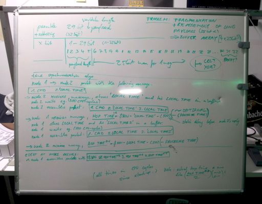
- T: Time synchronization paket
This message is defined in the example, in S_message.h of the RF24Network library:[7]
/**
* Sensor message (type 'S')
*/

struct S_message
{
  uint16_t temp_reading;
  uint16_t voltage_reading;
  S_message(void): temp_reading(0), voltage_reading(0), counter(next_counter++) {}
  char* toString(void);
};
This simply contains a temperature and voltage reading. These values are 8.8-bit “fixed point” values, the high byte is the decimal part and the low byte is the fractional part. For example, 3.5V is represented as 0×380. Also included is a method to convert it to a string for easy printing.
Draft for usage as a multi-phase alternator controller
Controlled parallel-serial generator switching system: A turbine could be actively regulated by Wilssen's load-balancing features, such as increasing or decreasing the load, up to the freewheeling no-load open-circuit state, or reconfiguring the alternator windings on the fly. As the coils are wound at least quadfilar, there are various possibilities to connect the windings.
Brainstorming (deprecated)
What micro controller platform should we choose for Wilssen?
- AVR: Atmel ATmega328 (AU, PU) (pico power series) (8bit)
- MSP430: Value line, e.g. MSP430G2231IPN14 (16bit)
One MSP430G2231IPN14 16bit micro controller could work for ages, at as low as 2V, it may consume 1 mW = 1/1000 W. Typical no-load best-case values from the MSP430 datasheet:
0.1 µA RAM retention
0.4 µA Standby mode (VLO)
0.7 µA real-time clock mode
220 µA / MIPS active
Excellent values! An 8-bit Arduino looks pretty old school against these numbers. ;-)
pro MSP430, con AVR/Arduino:
- the price! can be bought with a programmer for USD 4.30 vs Arduino USD 25.00 or a third-party Arduino for maybe USD 18.00 - This is a serious difference.
- even the single MCUs are cheaper, also, the AtMegas for an Arduino bootloader are hard to get.
- less external parts for operation at high speeds, Arduino/atmega168 and 328 need an external oscillator to operate at full speed (16 Mhz)
- runs stable over a wide range of input voltage down to 1.8V
- an excellent sleep mode with RAM retention at only 0.1µA and great power efficiency. 220µA in full operation mode is an excellent figure for off-grid low energy applications. Almost no load to the turbine. Can also be powered by a "Joule Thief" and a single old AA battery, or just two old AA cells in series (3V). That should last for ages, at a constant current of 0.25 mA and an old battery of 1000 mAh, the unit will still run for 180 days, and the MSP430 can be operated with a supply voltage as low as 1.8V.
con MSP430:
- less memory, but this depends on the package, (there are top-end msp430 processors which cost less than $1 vs an ever-expensive-avr)
- less libraries available, smaller community
A nice solution: => Write clean C-code and let it be compatible with MSP430 and AVR compilers. Some Arduino projects were easily ported to the MSP430.
Draft for a closed control loop:
example values: V_out = 16V V_sys = variable, depending on load V_gen = variable, depending on wind input and switching and system voltage
- monitor V_out. if V_sys less than Vout, then
- serialize the windings,
- still to little voltage? -> if generator-coil-form-1 and many points are broken out of the coil, then serialize them in a pattern to gain more voltage
- too much voltage? never mind, either wait for a small period of time because the rotor has a mass and stores kinetic energy, which first has to be converted by the "new serial-wound-generator". the speed will drop eventually and the voltage will stabilize itself, OR
- rapidly switch between parallel and serial modes (if the load, e.g. the synchronous rectifier, can cope with the spikes (inductive..) and has appropriate switching abilities) and thus form an sort of automatic pulse width modulated, regulated, operation mode.
- if V_sys + Vdelta,hysteresis >Vout, then
- switch to parallel mode
other cases:
- any of the voltages exceed e.g. 56V: emergency mode:
- either make the generator windings float or short them.
- !! shorting may not be an option. only with temperature control of the generator and the semiconductors due to the heat generated at a shortcut.!!
- If all batteries are loaded and the current user power consumption level is minimal, the power surplus of the turbine should be fed into high power LEDs, pointing upwards from the base, lighting the turbine. This adds to protect the system of an unbalanced situation, when more power is generated than reasonably consume- or storable and at the same time to signal, that we still have more energy to share, inviting people to join, in a friendly and beautiful manner.
- In general, LEDs should also be incorporated at the controller: the controller should have a mosfet-switched control output, one 3W RGB led should display the wind speed or the battery voltage.. (on a scale from red to green and strobe patterns)
- 'high-tech' electronic idea: dual rotor on single pole design, counter rotating, brush-less royer converter, doubled rpm, less poles, switching power supply is already build in due to the royer converter, coil-in-coil, core coupling, voltage output may be quite high from the start. lower electrical efficiency? downside: needs IP67 protected circuits on both the rotor and the stator of the royer converter. upside: output voltage could be regulated on-board. also, input voltage may be very low depending on the setup.
- variation: a rotor with lift-type wings on top and a rotor with drag-type wings at the bottom. thus the lower rotor gains speed at lower wind speeds but has a top end speed of approx. lift-type/2, while the lift-type wing still accelerates in high wind speed conditions.
- ↑ With one temperature read and transmitted every two minutes
- ↑ Printed Circuit Board
- ↑ 100x160mm - Eurocard is a European standard format for PCB cards, see http://en.wikipedia.org/wiki/Eurocard_(printed_circuit_board)]
- ↑ Printed Circuit Board
- ↑ http://maniacbug.wordpress.com/2012/03/30/rf24network/
- ↑ http://maniacbug.wordpress.com/2012/03/30/rf24network/
- ↑ http://maniacbug.wordpress.com/2012/03/30/rf24network/
