Nicht kategorisierte Dateien
Zur Navigation springen
Zur Suche springen
Unten werden bis zu 50 Ergebnisse im Bereich 1 bis 50 angezeigt.
Zeige (vorherige 50 | nächste 50) (20 | 50 | 100 | 250 | 500)
- 03 - Test01.pdf 1.239 × 1.754; 88 KB
- 03 - Test02.pdf 1.239 × 1.754; 361 KB
- 03 - Test03.pdf 1.239 × 1.754; 126 KB
- 1024-672-max.jpg 1.024 × 672; 108 KB
- 11b7b63b-79c6-4509-a9b4-ffafb52cfde9.png 1.907 × 949; 1,5 MB
- 20111228LXM8731 UZURI NOA -2 facebook3.jpg 446 × 796; 39 KB
- 201211270426 Wilssen core schematic4.png 4.095 × 3.150; 169 KB
- 20181108 InterimReport TasksREVONEER.pdf 1.240 × 1.754, 12 Seiten; 398 KB
- 20181206 InterimReport TasksREVONEER.pdf 1.240 × 1.754, 11 Seiten; 727 KB
- 2019-03 Zwischenbericht REVONEER OSE.pdf 1.240 × 1.754, 5 Seiten; 367 KB
- 2019-04 Zwischenbericht REVONEER OSE.pdf 1.240 × 1.753, 10 Seiten; 547 KB
- 2022 HSS Hauptlogo farbig 300dpi.png 1.043 × 489; 85 KB
- 2024-10-17 17-19-45.png 1.689 × 953; 1,44 MB
- 2024-10-17 17-27-16.png 1.753 × 988; 1,4 MB
- 2024-10-17 18-07-17.png 1.334 × 965; 1,11 MB
- 2024-10-17 18-12-07.png 1.704 × 992; 1,23 MB
- 2024-10-17 18-19-00.png 1.334 × 996; 1,17 MB
- 2024-10-17 18-22-01.png 1.330 × 980; 1,02 MB
- 2024-10-17 18-23-48.png 1.349 × 994; 1,12 MB
- 2024-10-17 18-29-11.png 1.348 × 987; 1,04 MB
- 3,6v.png 786 × 459; 34 KB
- 3-spannungen.png 1.099 × 635; 35 KB
- 405nm laser IMG 20120723 192129.jpg 1.920 × 1.080; 497 KB
- 424e892c-db2b-4a24-b2b4-481adcb5de4f.jpg 1.280 × 720; 70 KB
- 768c27b3-5a00-4b2f-b4fd-3a171502884f.png 1.054 × 742; 120 KB
- Abbildung 10 Anschluss BMS Leistungsboard.pdf 846 × 523; 1,06 MB
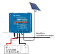
- Abbildung 10 Schnittstelle Laderegler Victron MPPT 100-15.svg 1.006 × 357; 29 KB
- Abbildung 11 Anschluss Laderegler MPPT 100-15.svg 732 × 669; 134 KB
- Abbildung 12.1 Hardwareänderungen LibreSolar BMS48V V1.pdf 400 × 372; 319 KB
- Abbildung 12.1 Hardwareänderungen LibreSolar BMS48V Var1.pdf 396 × 369; 319 KB
- Abbildung 13 3d Druckgehäuse.pdf 1.240 × 1.753; 10 KB
- Abbildung 13 3d Druckgehäuse BMS .pdf 977 × 652; 144 KB
- Abbildung 13 Aktualisierung der Firmware.svg 556 × 669; 30 KB
- Abbildung 13 Druckgehäuse 3d.pdf 977 × 652; 144 KB
- Abbildung 15 Arduinoplatine und deren Schnittstellen.png 700 × 793; 288 KB
- Abbildung 15 Arduinoplatine und deren Schnittstellen.svg 0 × 0; 2,1 MB
- Abbildung 15 Auslesen der UUID eines Kanales im VZ Frontend.pdf 804 × 526; 113 KB
- Abbildung 16 Mosfetplatine und deren Schnittstellen.svg 0 × 0; 4,01 MB
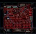
- Abbildung 17.1 Kombinierte Arduino- und Mosfetplatine.pdf 1.583 × 1.000; 25 KB
- Abbildung 17 Arduino- und Mosfetplatine im Gehäuse (Deckel geöffnet).pdf 1.666 × 819; 3,13 MB
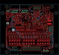
- Abbildung 18 Kombinierte Arduino- und Mosfetplatine.svg 1.027 × 601; 113 KB
- Abbildung 19 Hutschienengehäuse für Raspberry Pi.svg 741 × 371; 121 KB
- Abbildung 20 Schaltplan für Taster Herunterfahren und Reset Raspberry.svg 1.042 × 272; 145 KB
- Abbildung 28 Einstellungen MQTT Node IN und OUT.svg 730 × 434; 100 KB
- Abbildung 29 Anschlusssituation Temperatursensor LM 35.svg 261 × 265; 37 KB
Zeige (vorherige 50 | nächste 50) (20 | 50 | 100 | 250 | 500)


