Nicht kategorisierte Dateien
Zur Navigation springen
Zur Suche springen
Unten werden bis zu 100 Ergebnisse im Bereich 1 bis 100 angezeigt.
Zeige (vorherige 100 | nächste 100) (20 | 50 | 100 | 250 | 500)
 03 - Test01.pdf 1.239 × 1.754; 88 KB
 03 - Test02.pdf 1.239 × 1.754; 361 KB
 03 - Test03.pdf 1.239 × 1.754; 126 KB
 20111228LXM8731 UZURI NOA -2 facebook3.jpg 446 × 796; 39 KB
 201211270426 Wilssen core schematic4.png 4.095 × 3.150; 169 KB
 20181108 InterimReport TasksREVONEER.pdf 1.240 × 1.754, 12 Seiten; 398 KB
 20181206 InterimReport TasksREVONEER.pdf 1.240 × 1.754, 11 Seiten; 727 KB
 2019-03 Zwischenbericht REVONEER OSE.pdf 1.240 × 1.754, 5 Seiten; 367 KB
 2019-04 Zwischenbericht REVONEER OSE.pdf 1.240 × 1.753, 10 Seiten; 547 KB
 405nm laser IMG 20120723 192129.jpg 1.920 × 1.080; 497 KB
 Abbildung 10 Anschluss BMS Leistungsboard.pdf 846 × 523; 1,06 MB
 Abbildung 10 Schnittstelle Laderegler Victron MPPT 100-15.svg 1.006 × 357; 29 KB
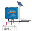 Abbildung 11 Anschluss Laderegler MPPT 100-15.svg 732 × 669; 134 KB
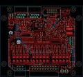 Abbildung 12.1 Hardwareänderungen LibreSolar BMS48V V1.pdf 400 × 372; 319 KB
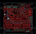 Abbildung 12.1 Hardwareänderungen LibreSolar BMS48V Var1.pdf 396 × 369; 319 KB
 Abbildung 13 3d Druckgehäuse.pdf 1.240 × 1.753; 10 KB
 Abbildung 13 3d Druckgehäuse BMS .pdf 977 × 652; 144 KB
 Abbildung 13 Aktualisierung der Firmware.svg 556 × 669; 30 KB
 Abbildung 13 Druckgehäuse 3d.pdf 977 × 652; 144 KB
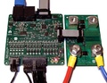
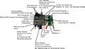
 Abbildung 15 Arduinoplatine und deren Schnittstellen.png 700 × 793; 288 KB
 Abbildung 15 Arduinoplatine und deren Schnittstellen.svg 0 × 0; 2,1 MB
 Abbildung 15 Auslesen der UUID eines Kanales im VZ Frontend.pdf 804 × 526; 113 KB
- Abbildung 16 Mosfetplatine und deren Schnittstellen.svg 0 × 0; 4,01 MB
 Abbildung 17.1 Kombinierte Arduino- und Mosfetplatine.pdf 1.583 × 1.000; 25 KB
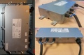
 Abbildung 17 Arduino- und Mosfetplatine im Gehäuse (Deckel geöffnet).pdf 1.666 × 819; 3,13 MB
 Abbildung 18 Kombinierte Arduino- und Mosfetplatine.svg 1.027 × 601; 113 KB
 Abbildung 19 Hutschienengehäuse für Raspberry Pi.svg 741 × 371; 121 KB
 Abbildung 20 Schaltplan für Taster Herunterfahren und Reset Raspberry.svg 1.042 × 272; 145 KB
 Abbildung 28 Einstellungen MQTT Node IN und OUT.svg 730 × 434; 100 KB
 Abbildung 29 Anschlusssituation Temperatursensor LM 35.svg 261 × 265; 37 KB
 Abbildung 2 Mietobjekt ohne und mit PV Speichersystem-001.pdf 1.004 × 412; 522 KB
 Abbildung 2 Mietobjekt ohne und mit PV Speichersystem.pdf 1.089 × 580; 8,07 MB
 Abbildung 30.1 Heizstabregelmodul.pdf 1.753 × 1.240; 196 KB
 Abbildung 30 Heizstabmodul.png 467 × 146; 131 KB
 Abbildung 30 Heizstabplatine.svg 466 × 146; 1,28 MB
 Abbildung 31.1 Modbus-SML PCB.pdf 702 × 467; 46 KB
 Abbildung 31.2 SML Zähler.pdf 376 × 502; 61 KB
 Abbildung 31.3 IR Lese-Schreibkopf.pdf 1.106 × 415; 45 KB
 Abbildung 31 Modbuszähler 3 Phasen Zähler.svg 726 × 391; 899 KB
 Abbildung 32 Modbuszähler Solar 1 Phasen Zähler.svg 224 × 896; 146 KB
 Abbildung 33 CAT 5 Adapter.svg 1.024 × 399; 660 KB
 Abbildung 33 CAT 5 Adapter mit Minischraubklemmen.svg 744 × 1.052; 144 KB
 Abbildung 33 CAT 5 mit Minischraubklemmen.svg 1.052 × 744; 660 KB
 Abbildung 33 Minischraubklemmen.svg 1.052 × 744; 660 KB
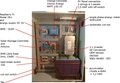 Abbildung 34.1 Komponentenanordnung 3. Prototyp.pdf 1.100 × 762; 147 KB
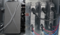 Abbildung 34 Wechselrichteranordnung im Schaltschrank.svg 737 × 436; 941 KB
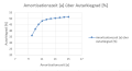 Abbildung 35 Systemaulsegung anhand des Exceltools.svg 726 × 391; 20 KB
 Abbildung 3 Aufbau des Systems.svg 1.011 × 488; 204 KB
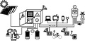 Abbildung 3 Systemaufbau.pdf 528 × 255; 42 KB
 Abbildung 4 Cortex ST-Link Adapter.pdf 1.110 × 369; 260 KB
 Abbildung 5 Systemkomponenten 2.svg 566 × 388; 180 KB
 Abbildung 5 Systemkomponenten 3.svg 1.034 × 708; 186 KB
 Abbildung 5 Systemkomponenten Schnittstellen.svg 566 × 388; 180 KB
 Abbildung 5 Systemkomponenten und deren Schnittstellen.pdf 944 × 646; 34 KB
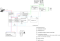 Abbildung 5 Systemkomponenten und deren Schnittstellen png.png 567 × 388; 53 KB
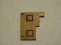 Abbildung 5 Unterlegscheibe aus Holz.pdf 491 × 368; 885 KB
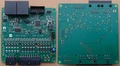 Abbildung 7 Hardwareänderungen am BMS Controllerboard.pdf 673 × 368; 410 KB
 Abbildung 8 Lithium-Eisen-Mangan-Phosphat Akkumulator INNO-LFMP 60 AH.pdf 1.105 × 368; 391 KB
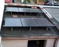 Abbildung 9.4 Solarmodulinstallation 3. Prototyp.pdf 343 × 272; 1,19 MB
 Abbildung 9.4 Solarmodulinstallation 3. Prototyp.svg 744 × 1.052; 1,42 MB
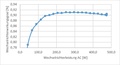
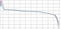 Abbildung 9 Entladungskurve gemessen bei einer konstanten Last von 105W.pdf 1.141 × 553; 83 KB
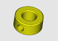 Adjustring8mm.png 718 × 515; 25 KB
 Agrokruh photocopy placeholder.jpg 291 × 333; 25 KB
 Agrokruh photocopy placeholder.png 291 × 333; 69 KB
 Agrokruh placeholder.png 400 × 475; 178 KB
 Ai thinker esp-01.pdf 1.275 × 1.650, 19 Seiten; 854 KB
 Aircage eh.png 792 × 621; 30 KB
 Alex Shure.jpg 446 × 796; 39 KB
 Alex Shure 100px.jpg 100 × 132; 25 KB
 All angles.png 951 × 503; 15 KB
 All flatplates.png 953 × 569; 34 KB
 Andreas Gmeiner.png 310 × 465; 707 KB
 Anschlussmasse.jpg 1.280 × 960; 67 KB
 Archimedes screw London 59MWh year.png 128 × 194; 34 KB
 Arduino-mega.png 866 × 710; 31 KB
 Arduino nano.png 749 × 718; 18 KB
 Aron Homberg.jpg 140 × 185; 30 KB
 Ass bottom.jpg 1.280 × 960; 100 KB
 Assembly 01.png 811 × 685; 59 KB
 Auswertung der Zugänglichkeitsverteilung.svg 602 × 344; 13 KB
 Auswertung grob Arbeitsplattformen 6-7Mai2017-aktualisiert.pdf 1.239 × 1.754, 5 Seiten; 49 KB
 Automobile 50pxh.png 66 × 50; 6 KB
 Avatar timo.png 170 × 170; 69 KB
 Bachelor Thesis Eric Roder Ressourcenbasierte Wirtschaft.pdf 1.239 × 1.754, 86 Seiten; 492 KB
 Bachelorarbeit michael weh.pdf 1.240 × 1.753, 62 Seiten; 3,25 MB
 Back-icon.png 28 × 25; 1 KB
 Backbone1b.odg ; 15 KB
 Backbone1b.png 794 × 1.123; 90 KB


.svg)


_und_Stromverbrauch_(blau)-001.jpg)
Zeige (vorherige 100 | nächste 100) (20 | 50 | 100 | 250 | 500)